The Vector Control Revolution
Driving a Brushless DC (BLDC) or Permanent Magnet Synchronous Motor (PMSM) efficiently is a major engineering hurdle. Basic electronic speed controllers (ESCs) utilize **trapezoidal (six-step) commutation**, which energizes only two phases at any instant, leaving the third floating. While electronically simple, this abrupt state switching creates major **torque ripple**, structural vibrations, and heat losses.
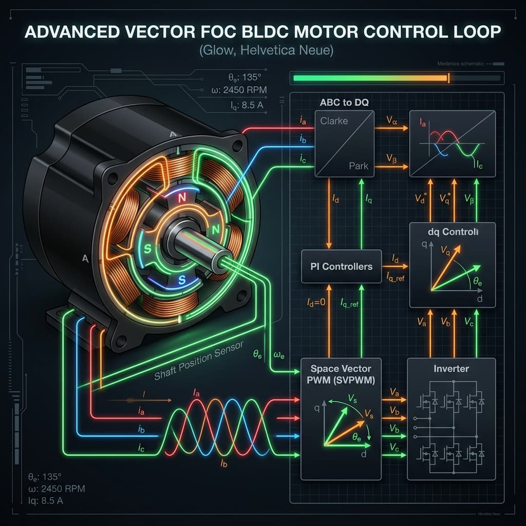
The industry standard solution for precision motion is Field Oriented Control (FOC). By continuously measuring phase currents and rotor orientation angles, FOC shapes three-phase currents into a smooth, rotating sinusoidal magnetic vector that is maintained exactly perpendicular to the rotor\'s magnetic field, maximizing torque generation per watt.
The Mathematical Transformations
Decoupling phase currents requires real-time coordinate transformations running inside high-frequency interrupts (e.g. 20kHz).
1. The Clarke Transform: Converts three-phase current vectors (Ia, Ib, Ic) separated by 120 degrees into a two-axis stationary orthogonal frame (I-alpha, I-beta).Ialpha = Ia;
Ibeta = (Ia + 2 * Ib) / sqrt(3);
2. The Park Transform: Rotates the stationary I-alpha and I-beta axes onto a coordinate system revolving dynamically with the rotor angle (Theta). This yields:
- **Iq** (Quadrature Current): Aligns perpendicular to the rotor magnets to generate pure rotational **torque**.
- **Id** (Direct Current): Aligns parallel to the rotor magnets, generating pure **magnetic flux** (typically controlled to 0A unless field-weakening high speeds are needed).
Id = Ialpha * cos(Theta) + Ibeta * sin(Theta);
Iq = -Ialpha * sin(Theta) + Ibeta * cos(Theta);Cascaded Control Loop Architecture
FOC implements a series of **cascaded PID loops** operating at different temporal scales:
- **Current Loops (Fastest, ~20kHz)**: Two separate PID controllers monitor Id and Iq. They output target stator control voltages Vd and Vq.
- **Velocity Loop (Medium, ~1kHz)**: Compares measured encoder speed to target speed and outputs the target torque current (Iq_ref) to the current loop.
- **Position Loop (Slowest, ~100Hz)**: Compares current position to target coordinate, outputting target velocity to the velocity loop.
Once Vd and Vq are computed, they are transformed back using the Inverse Park transform to stationary V-alpha and V-beta. These stationary orthogonal vectors are fed to the **Space Vector PWM (SVPWM)** algorithm, which maps the voltages into optimal duty cycle timings for the six inverter MOSFET switches.
Mistakes to Avoid in FOC Implementations
❌ Poor current shunt measurement synchronization
Because phase currents are highly distorted by high-frequency PWM switching (typically 20kHz), the ADCs must be triggered with sub-microsecond precision at exact midpoints of the PWM cycles (center-aligned mode). Sampling current randomly during a MOSFET transition edge injects massive switching noise, corrupting the Park transforms and destabilizing the loops.
❌ Ignoring the integral windup limit in fast current PIDs
Under sudden high load shifts, current loops can saturate, causing the PID\'s integral term to continue accumulating error (windup). When the load drops, the accumulated error causes huge current spikes and severe control oscillations. Always clamp the integral sum bounds strictly to your maximum inverter voltage limits.
Frequently Asked Questions
What is Sensorless FOC?
Sensorless FOC eliminates physical encoders or Hall sensors, relying instead on high-speed mathematical algorithms ("sliding mode observers" or "flux observers") to estimate rotor position by tracking back-EMF vectors inside active phases, which works beautifully at high speeds but lacks starting torque.
Why is Space Vector PWM (SVPWM) better than Sinusoidal PWM (SPWM)?
SVPWM utilizes the star center point voltage shifting concept to maximize DC bus voltage utilization. It delivers 15.5% higher peak output phase voltage than standard SPWM, reducing harmonic distortion and allowing motors to run significantly cooler.
What is Field Weakening in FOC?
Field weakening is an advanced technique where developers inject a negative direct current (Id < 0) into the stator. This generates a magnetic field opposing the permanent rotor magnets, reducing total back-EMF and allowing the motor to spin far beyond its physical voltage speed limit (often used in EV drivetrains).
Conclusion
Implementing FOC vector algorithms is the final step in transition from entry-level electronics to elite mechatronics systems design. By mastering Clarke/Park mathematics and SVPWM switching, you unlock high-efficiency, smooth control for electric vehicles, heavy drones, and industrial cobots. Map your path further by diving into our motor control drives career roadmap!