Failure Mode Analysis (FMA) for Hall Circuits
When building or debugging magnetic sensing circuits, engineers face a few common failure modes:
❌ Output Stuck at VCC (5V/3.3V)
The sensor never triggers. This usually happens when the wrong magnet pole is facing the sensor. Unipolar switches only respond to a South pole facing the branded face of the TO-92 package. Flip the magnet to resolve this. Another cause is insufficient magnetic flux density (magnet too far away to hit the Magnetic Operate Point BOP).
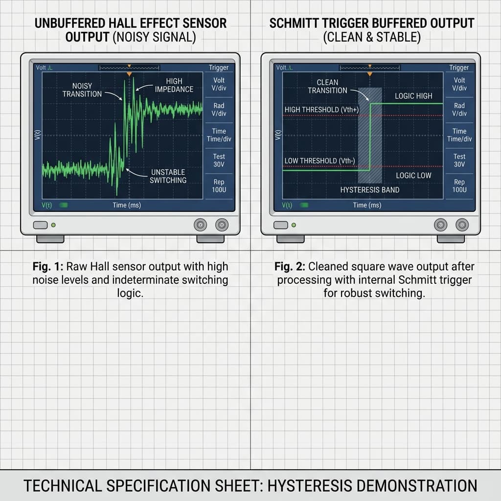
❌ Chattering & Multiple Triggering (Noise)
At the boundary of detection, the output rapidly toggles between High and Low due to magnetic field ripples or electrical noise. This causes double pulses and false interrupts in tachometer code.
- Pull-up resistors define high-state voltage thresholds.
- Schmitt trigger thresholds prevent sensor output chattering.
- Decoupling capacitors filter electromagnetic line interference.
Selecting the Right Pull-Up Resistor
Most digital Hall sensors (such as A3144 or US1881) use an open-collector output. The internal transistor pulls the output to Ground when active, but floats disconnected when inactive. A pull-up resistor is required to pull the line High.
- 10kΩ Resistor (Standard): Excellent for low frequency (<10 kHz) and short wire runs (<1 meter). Minimizes current draw.
- 4.7kΩ to 2.2kΩ Resistors (High-speed/Long runs): Essential for high-speed motor encoders or when the sensor is located far from the controller. Lower resistance pulls the line High faster, countering cable capacitance which rounds off square wave edges.
Schmitt Trigger Hysteresis
High-quality digital Hall ICs feature an integrated Schmitt trigger. This creates a magnetic gap between the Operate point (BOP) and the Release point (BRP).
For example, the sensor may turn ON (pull output LOW) at +100 Gauss (South pole). It will not turn OFF (release output to HIGH) until the field drops below +40 Gauss. This 60 Gauss difference is hysteresis. If a magnet hovers at 95 Gauss, small magnetic variations won't cause false triggers because the field has to drop all the way below 40 Gauss to release.
Noise Filtering and Debouncing
In motor control and automotive environments, electromagnetic interference (EMI) from motors and switching currents causes voltage spikes. Follow these rules to clean up the signal:
- Decoupling: Place a 100nF ceramic capacitor across the VCC and GND pins directly at the sensor. This provides local filtering, preventing power line spikes from triggering the internal comparator.
- Shielding: Run sensor signals through shielded or twisted-pair cables if wire lengths exceed 1 meter.
- Software Debouncing: Implement a software dead-time check inside the interrupt routine to reject false triggers.
// Software Interrupt Debouncing Example for RPM Counters
volatile unsigned long pulseCount = 0;
volatile unsigned long lastTriggerTime = 0;
const unsigned long DEBOUNCE_DELAY = 3; // 3 ms dead-time (filters noise up to 20,000 RPM)

void IRAM_ATTR countPulseISR() {
  unsigned long currentTime = millis();

  // Only increment if current interrupt is at least 3ms after the last one
  if (currentTime - lastTriggerTime >= DEBOUNCE_DELAY) {
    pulseCount++;
    lastTriggerTime = currentTime;
  }
}
Hobbyist & Industrial Hall Calibration Tools in India
Sourcing passive resistors, ceramic capacitors, digital oscilloscopes, and replacement Hall sensors to troubleshoot and calibrate circuits is easy across Indian electronics hubs:
Mumbai
Lamington Road shops carry massive stocks of passive component assortments (4.7k resistors, 100nF capacitors) and budget digital oscilloscopes.
Delhi
Purchase electronic prototyping kits, shielded signal cables, and replacement Hall ICs in Lajpat Rai Market.
Bangalore
SP Road is India's top location for buying professional-grade multimeters, diagnostic tools, and high-temp Hall sensors.
Hyderabad
Find pull-up resistor packs, breadboard wires, and ceramic capacitor kits in Koti's Gujarati Gali.
Pune
Engineering diagnostic tools and passive electronics assortments are easily bought in Budhwar Peth.
Chennai
Visit Ritchie Street for shielded cabling, heat shrink tubing, active test equipment, and sensor modules.
Kolkata
Chandni Chowk Market provides cheap replacement ICs, soldering kits, and basic multimeters.
Frequently Asked Questions
Why is my Hall effect sensor outputting 5V constantly and never changing state?
This is usually caused by one of three issues: 1) The magnet polarity is reversed. Unipolar sensors (like the A3144) only trigger when the South pole faces the branded front of the sensor. If the North pole faces it, nothing happens. 2) The magnet is too weak or too far away, failing to reach the Magnetic Operate Point (Bop). 3) You are using a latching sensor (like the US1881) which requires an opposite North pole to turn off; if you only pass a South pole, it latches ON (LOW) and stays there.
What value pull-up resistor should I use for a digital Hall sensor?
A 10kΩ resistor is standard for low-frequency operations (below 10 kHz) and short wire lengths. However, for high-frequency speed sensors or long cables, a smaller pull-up resistor like 4.7kΩ or 2.2kΩ is recommended. This draws more current, which decreases the RC time constant of the cable capacitance, resulting in cleaner, sharper square wave transitions.
What is Schmitt trigger hysteresis and why is it important in Hall ICs?
Hysteresis is the difference between the magnetic Operate Point (Bop) and the Release Point (Brp). A built-in Schmitt trigger ensures that if a magnet hovers right at the trigger threshold, electrical or magnetic noise won't cause the sensor output to cycle rapidly between HIGH and LOW (chattering). The magnetic field must drop below Brp before the sensor turns off, resulting in clean, singular digital transitions.
Why am I getting false triggers and double pulses in my Arduino code?
Double pulses usually occur due to electromagnetic interference (EMI) from nearby motors or inductive loads, or when the magnet passes the sensor too slowly. To resolve this, run a 100nF decoupling capacitor across VCC and GND directly at the sensor pins, use shielded cable for the signal wire, and add a brief software dead-time check (debouncing) in your interrupt routine.
What is the difference between Bop and Brp?
Bop is the Magnetic Operate Point — the magnetic flux density (measured in Gauss or Tesla) required to turn the sensor output ON. Brp is the Magnetic Release Point — the flux density required to turn the sensor output OFF. The gap between them is the hysteresis, preventing signal oscillation.
Conclusion
Troubleshooting and calibrating Hall effect sensors is a matter of electrical discipline and mechanical alignment. By using external pull-up resistors configured for your signal speeds, placing decoupling capacitors close to power inputs, and leveraging software debounce strategies, you can resolve noisy signals and false triggers to secure high-speed magnetic data integrity.
Ready to learn more? Read about digital signal pull-up mechanics in our Transistor switching guide, configure stable voltage dividers with the Voltage Divider Calculator, or trace general principles in the General Hall Effect overview.
📚 References & Sources
Related Resources
How Transistors Work
Master open-collector states, base switching, and pull-up resistor calculations.
Voltage Divider Calculator
Compute pull-up voltage levels and load resistance offsets.
How Capacitors Work
Learn about decoupling capacitor filtering and transient voltage absorption.
How Hall Effect Sensors Work
Revisit the fundamentals of Lorentz force and Hall voltage.