How Pull-Up Resistors Work: Direct Definition
- [How Pull-Up Resistors Work] [connects] [circuit theory to practical wiring]
- [how pull-up resistors work] [improves] [debugging accuracy and component selection]
- [Volt X guides] [link] [related tools, sensors, and embedded systems]
Why Floating Inputs Are a Problem
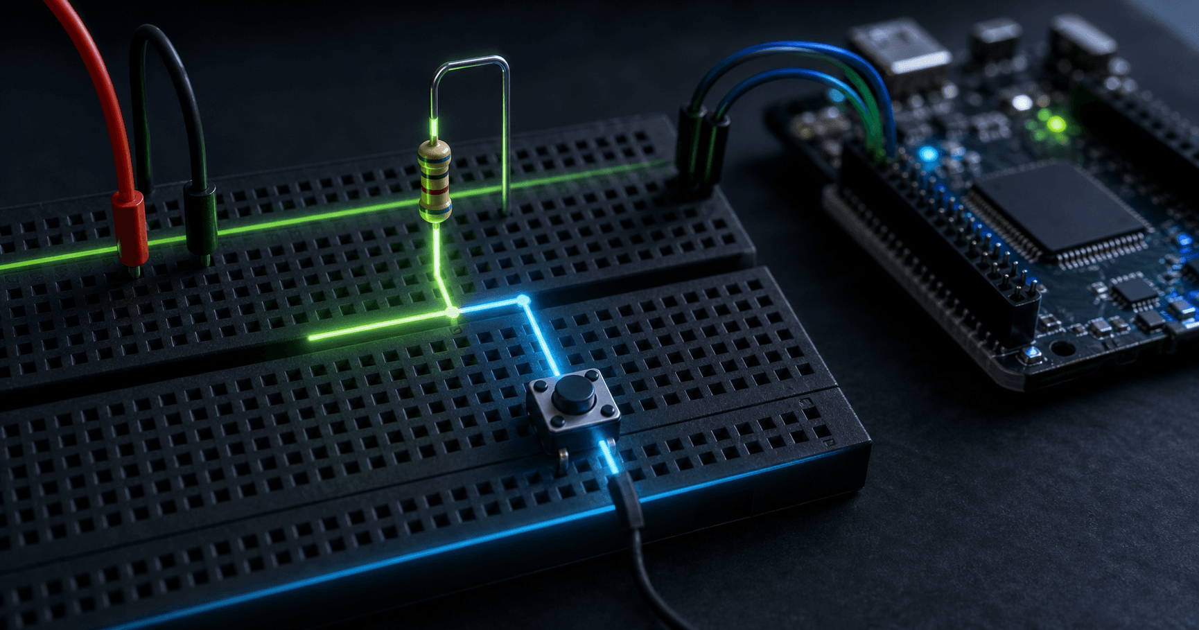
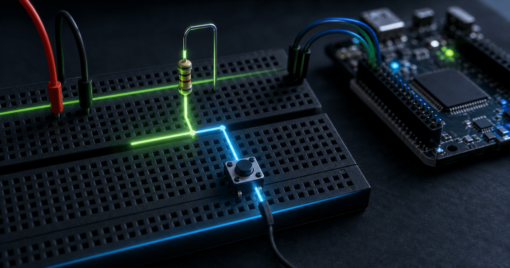
A digital input pin has extremely high impedance. If nothing drives it high or low, nearby electric fields and leakage currents can make it randomly read both states. A pull-up resistor gently connects the input to VCC so the default state is high until another device actively pulls it low.
Button Wiring with Pull-Ups
The classic button circuit connects one side of the button to ground and the other side to the input pin. A pull-up resistor connects that input to VCC. When the button is open, the pin reads high. When pressed, the button creates a much lower resistance path to ground, so the pin reads low.
Choosing a Pull-Up Value
Lower resistance gives faster rising edges and stronger noise immunity but wastes more current when pulled low. Higher resistance saves current but creates slower edges and more sensitivity to leakage. Buttons often use 10 kOhm. I2C buses may need 2.2 kOhm to 4.7 kOhm depending on bus capacitance and speed.
Internal vs External Pull-Ups
Many microcontrollers include internal pull-ups, often around 20 kOhm to 50 kOhm. They are convenient for buttons and configuration pins but may be too weak for fast buses or long wires. External pull-ups provide predictable values and better signal integrity.
Parts and Modules Availability in India
For student labs and prototype builds in India, look for the exact voltage rating, interface level, package type, and module quality before buying. SP Road in Bangalore, Lamington Road in Mumbai, Lajpat Rai Market in Delhi, Ritchie Street in Chennai, Koti in Hyderabad, Budhwar Peth in Pune, and Chandni Chowk Market in Kolkata commonly stock beginner-friendly modules and passives.
Frequently Asked Questions
What does a pull-up resistor do?
A pull-up resistor defines a default high logic state for an input or open-drain signal. It prevents floating pins and lets another device safely pull the line low when needed.
Why do pull-up resistors matter in electronics?
It matters because small interface decisions can change accuracy, reliability, safety, and debugging time. Understanding the fundamentals helps you choose values, modules, and wiring methods intentionally.
What is the most common pull-up resistor mistake?
The most common mistake is treating the circuit as ideal. Real components have limits such as input impedance, noise, timing, voltage ratings, heating, drift, or contact behavior.
Can beginners use this in Arduino projects?
Yes. Start with a low-voltage breadboard setup, verify ratings, use conservative resistor values or modules, and test one signal at a time before connecting expensive boards or high-power loads.
Conclusion
How Pull-Up Resistors Work becomes much easier when you separate the ideal idea from the physical limits. Use the specs above, test with conservative values, and connect this topic with related Volt X guides before scaling a prototype into a finished build.