Quick Definition
- [TCRT5000 sensor] [measures] [surface reflectance]
- [Sensor spacing] [sets] [line position resolution]
- [Arduino steering code] [converts] [left-right reflectance error into motor speed]
Array Layout: Why Five Sensors Beats Two
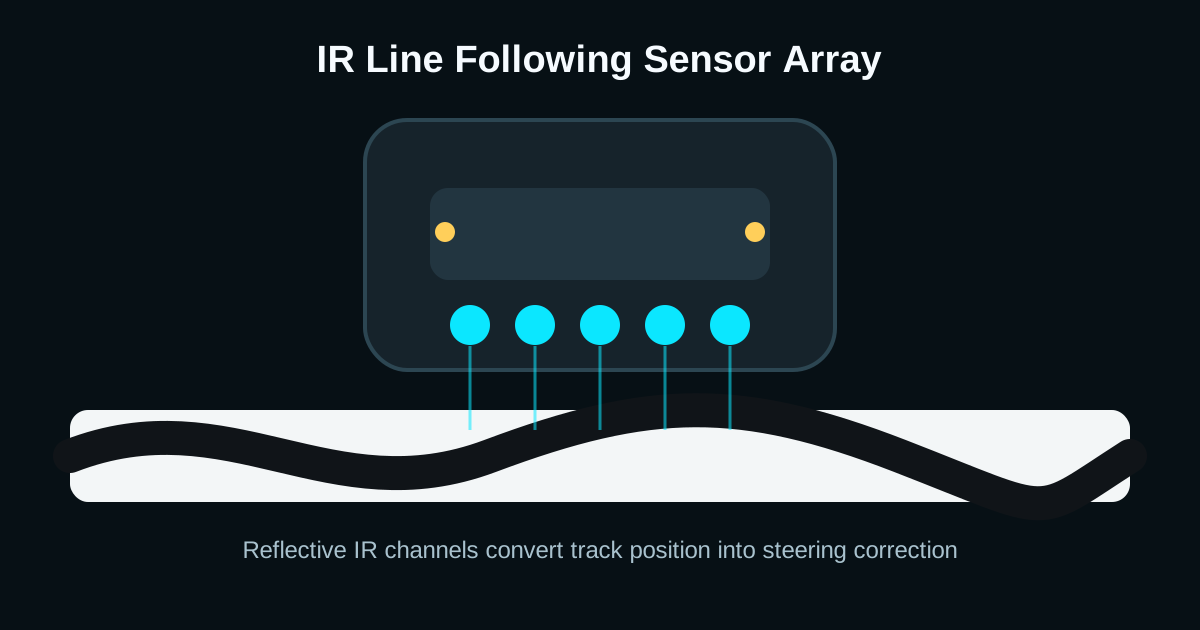
A two-sensor robot can follow a simple line, but it only knows left, right, or lost. A five-sensor array gives the controller a graded position estimate: far left, left, center, right, and far right. That extra information makes turns smoother and prevents the robot from oscillating at speed.
Keep the sensors close to the floor and aligned perpendicular to the direction of travel. If the front edge of the robot has too much overhang, the array reads the line too late and the chassis will overshoot corners.
- Use 8-15 mm spacing for common 18-20 mm electrical tape tracks.
- Mount the array 3-8 mm above the surface for strong reflection.
- Shield the sides from sunlight using a small black printed bracket or foam skirt.
Threshold Tuning: Digital vs Analog Readings
Digital line modules use a comparator and potentiometer to decide when a sensor is over the line. That is easy to wire, but it hides useful reflectance detail. Analog arrays expose the raw values, so you can calibrate black and white levels in software.
A good calibration routine records the minimum and maximum value for each sensor while the robot is swept across the track. Then every reading can be normalized before calculating the line position.
Arduino Steering Logic for a Five-Sensor Array
Start with proportional steering before moving to full PID. The code below computes a weighted line position from five digital sensors and slows one motor based on the error.
const int irPins[5] = {2, 3, 4, 5, 6};
const int weights[5] = {-2, -1, 0, 1, 2};

void loop() {
  int active = 0;
  int sum = 0;

  for (int i = 0; i < 5; i++) {
    int onLine = digitalRead(irPins[i]) == HIGH;
    active += onLine;
    sum += onLine * weights[i];
  }

  if (active == 0) {
    // Last-direction recovery belongs here.
    return;
  }

  float error = (float)sum / active;
  int correction = error * 45;
  setMotors(160 - correction, 160 + correction);
}
Frequently Asked Questions
How many IR sensors are best for a line follower?
Three sensors are enough for slow robots, but five sensors give smoother turns and better recovery. Fast robots usually use six to eight analog sensors for higher line-position resolution.
Why does my line follower shake left and right?
The sensors are probably too far apart, mounted too high, or using binary steering at too much speed. Lower the array, reduce motor speed, and calculate a proportional correction from multiple sensors.
Should the black line read HIGH or LOW?
It depends on the module comparator. Many TCRT5000 modules output one logic state for high reflection and the opposite for black tape. Calibrate in code instead of assuming a fixed polarity.