Arduino Mega 2560 R3
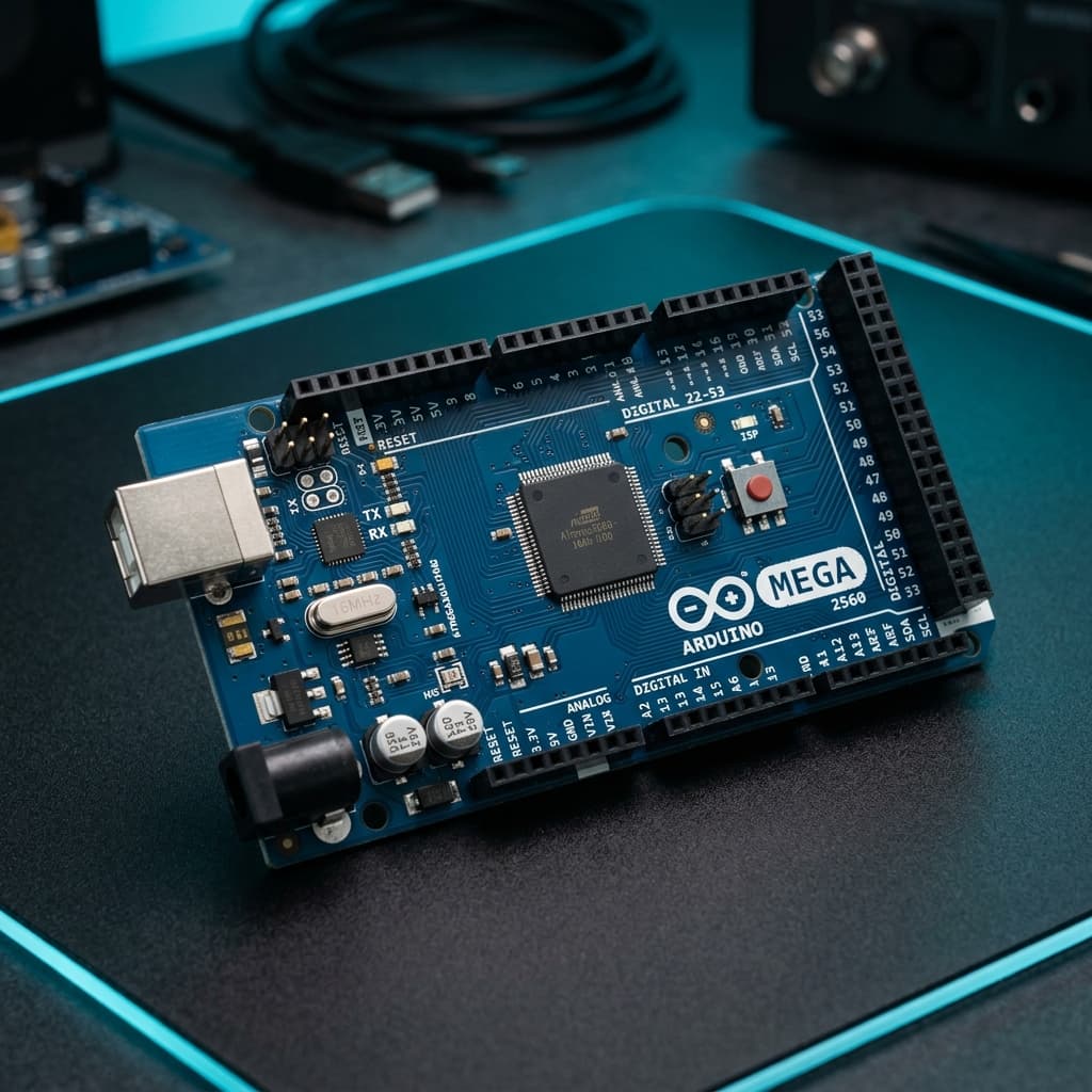
What is Arduino Mega 2560 R3?
The Arduino Mega 2560 R3 is a heavy-duty microcontroller board based on the Microchip ATmega2560 8-bit AVR processor. Operating at 16 MHz with 5V logic, it is engineered specifically for complex projects that exceed the memory, I/O pin count, and peripheral buses of the standard Arduino Uno.
With 54 digital input/output pins (including 15 hardware PWM outputs), 16 analog inputs, 256 KB of Flash memory, and 4 dedicated hardware UART serial ports, the Mega 2560 is the industry standard for 3D printer controllers (driving RAMPS 1.4 shields), multi-axis CNC machines, and multi-motor robotics platforms.
Technical Specifications
Recommended Applications & Industry Uses
3D Printers & CNC Controllers
Industry benchmark for RAMPS 1.4/1.6 shields, coordinating 5 stepper motor axes, heated beds, and multiple extruder PID thermistors.
Multi-Axis Robotic Arms & Inverse Kinematics
Drives 15+ servos and high-power PWM motor controllers concurrently while processing end-effector encoder ticks and limit switches.
Industrial PLC & SCADA Automation
Monitors banks of 24V isolated sensors, triggers relay banks, and runs Modbus RTU communications across its 4 independent hardware UARTs.
Complex Multi-Sensor Telemetry Stations
Samples 16 independent analog input lines without needing external I2C/SPI multiplexers, ideal for meteorological and energy monitoring.
Key Features & Architectural Highlights
Massive Digital I/O
54 Digital PinsConnect dozens of limit switches, motor drivers, buttons, and status displays without requiring external shift registers or I2C port expanders.
Quad Serial Ports
4 Hardware UARTsFeatures Serial, Serial1, Serial2, and Serial3. Connect GPS receivers, GSM modems, Bluetooth bridges, and PC consoles simultaneously without software serial lag.
8x More Flash Memory
256 KB Flash StorageProvides 256 KB of program memory (8x more than the Uno) and 8 KB SRAM, accommodating large GUI font buffers and complex state machines.
3D Printer & CNC Shield Host
RAMPS 1.4 CompatibleAccepts the popular RAMPS 1.4 shield to drive up to 5 A4988/TMC2209 stepper motors, heated bed thermistors, and Marlin firmware.
16 Dedicated Analog Pins
16 ADC Inputs16 analog-to-digital converter channels (A0 to A15) providing 10-bit resolution across the full 0–5V range for complex sensor arrays.
15 Hardware PWM Timers
15 PWM Channels15 independent 8-bit hardware PWM outputs across pins 2–13 and 44–46 for multi-servo kinematics and smooth DC motor speed regulation.
Pin Configuration & Peripheral Layout
Digital I/O & Extended Headers (D0 - D53)
54 digital pins capable of sourcing/sinking up to 20mA each at 5V logic.
- Pins D2–D13 & D44–D46 provide 15 independent hardware PWM outputs
- Pins D22–D53 arranged in a dual-row header at the rear edge for high-density wiring
- External interrupt pins: D2 (INT4), D3 (INT5), D18 (INT3), D19 (INT2), D20 (INT1), D21 (INT0)
Analog Input Matrix (A0 - A15)
16 high-impedance analog input channels connected to an internal 10-bit ADC.
- Reads analog signals from 0V to 5V with 1024 discrete resolution steps
- Selectable internal analog reference: DEFAULT (5V), INTERNAL1V1 (1.1V), or INTERNAL2V56 (2.56V)
- Pins A0 to A15 can also double as standard digital input/output pins if needed
Dedicated Hardware Buses & Power
Multiple independent serial transceivers, SPI, I2C, and regulated power lines.
- 4 UART pairs: Serial (D0/D1), Serial1 (D19/D18), Serial2 (D17/D16), Serial3 (D15/D14)
- I2C bus located on pins D20 (SDA) and D21 (SCL) with pull-ups
- Hardware SPI bus located on pins D50 (MISO), D51 (MOSI), D52 (SCK), and D53 (SS)
Communication Protocols
Hardware UART 0
D0 (RX0) & D1 (TX0)
Primary hardware serial port connected to the ATmega16U2 USB chip for flashing and PC Serial Monitor.
Hardware UART 1
D19 (RX1) & D18 (TX1)
Second full-duplex hardware serial port, ideal for GPS modules (u-blox NEO-6M) or Bluetooth bridges.
Hardware UART 2
D17 (RX2) & D16 (TX2)
Third hardware serial port, frequently used for Nextion HMI touch displays or secondary microcontrollers.
Hardware UART 3
D15 (RX3) & D14 (TX3)
Fourth serial port for telemetry radios, SIM800L cellular modems, or industrial RS-485 transceivers.
Hardware I2C (TWI)
D20 (SDA) & D21 (SCL)
Two-wire serial bus supporting standard 100 kHz and fast 400 kHz modes for RTC clocks and OLED screens.
Hardware SPI Bus
D50 (MISO), D51 (MOSI), D52 (SCK), D53 (SS)
High-speed 8 MHz SPI bus routed to the rear headers and central ICSP header for SD cards and Ethernet shields.
Advanced Topics & Expert Knowledge
Non-Blocking Multi-UART Routing
Stream data from multiple sensors simultaneously across Serial1, Serial2, and Serial3 using circular ring buffers without packet collision.
Pro tip: Hardware FIFO buffers on all 4 UARTs eliminate the high CPU interrupt latency inherent to SoftwareSerial.
6 Hardware Timers (Timer 0 - 5)
Features four 16-bit timers (Timer1, Timer3, Timer4, Timer5) and two 8-bit timers (Timer0, Timer2) for ultra-precise multi-motor pulse generation.
Pro tip: Marlin 3D printer firmware uses Timer1 for high-frequency stepper pulses up to 40,000 steps/sec.
External SRAM Bus Interface
The ATmega2560 features an external memory interface (XMEM) allowing you to connect external parallel SRAM chips up to 64 KB across Port A and Port C.
Pro tip: Crucial for retro computing emulators and high-resolution camera image buffers on 8-bit AVR.
Marlin Firmware Kinematics
Deploy Marlin 2.0 to coordinate 5 stepper motors, dual hotend heaters, bed leveling probes, and optical endstops for Cartesian and CoreXY printers.
Pro tip: Use TMC2209 stepper drivers in UART mode on the Mega for ultra-quiet sensorless homing.
Port-Wide Direct Register Writes
Access entire 8-pin ports (PORTA, PORTC, PORTL) simultaneously to clock 8-bit parallel TFT displays at over 20 frames per second.
Pro tip: Parallel 8-bit display shields plug directly into the rear double-row header for zero-wire display setups.
ATmega16U2 DFU Keyboard/Joystick Mode
Flash the onboard ATmega16U2 USB chip with custom DFU firmware to make the Mega appear as a native USB flight joystick or MIDI controller.
Pro tip: Short the reset and ground solder pads behind the USB jack to put the 16U2 chip into DFU bootloader mode.
Recommended Applications & Industry Uses
3D Printers & CNC Controllers
Industry benchmark for RAMPS 1.4/1.6 shields, coordinating 5 stepper motor axes, heated beds, and multiple extruder PID thermistors.
Multi-Axis Robotic Arms & Inverse Kinematics
Drives 15+ servos and high-power PWM motor controllers concurrently while processing end-effector encoder ticks and limit switches.
Industrial PLC & SCADA Automation
Monitors banks of 24V isolated sensors, triggers relay banks, and runs Modbus RTU communications across its 4 independent hardware UARTs.
Complex Multi-Sensor Telemetry Stations
Samples 16 independent analog input lines without needing external I2C/SPI multiplexers, ideal for meteorological and energy monitoring.
Programming on Arduino Mega 2560 R3
📚 Official Citations & Technical References
To ensure the absolute accuracy and reliability of this guide, all specifications, pinouts, and register settings have been cross-verified with official manufacturer documentation:
Related Resources
Frequently Asked Questions
When should I choose the Arduino Mega over the Arduino Uno?
Choose the Mega when your project requires more than 14 digital pins, more than 6 analog inputs, multiple hardware serial communication lines (like GPS + Bluetooth), or large Flash memory capacity for 3D printers and graphical displays.
Can the Arduino Mega 2560 run shields designed for the Arduino Uno?
Yes! The Mega’s pin header layout preserves the standard Uno shield footprint. The only caveat is that SPI pins (MOSI, MISO, SCK) on the Mega are on pins 50–52 instead of 11–13, so SPI shields must use the 6-pin ICSP header.
How much current can the Arduino Mega 2560 provide from its 5V pin?
When powered via USB, the 5V pin can provide up to 500mA (protected by an onboard resettable polyfuse). When powered through the barrel jack with 7V–12V, the onboard linear regulator can deliver up to 800mA.