ESP8266 NodeMCU V3 & ESP-12E
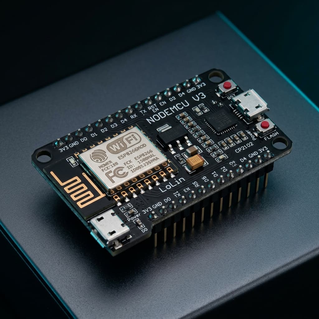
What is ESP8266 NodeMCU V3 & ESP-12E?
The ESP8266 NodeMCU V3 is an open-source, sub-$3 IoT development board built around the Espressif ESP-12E metallic-shielded Wi-Fi module. Powered by a 32-bit Tensilica Xtensa L106 processor running at 80 MHz (overclockable to 160 MHz), it sparked the modern DIY internet-of-things revolution.
Equipped with 4 MB of external SPI flash memory, a full integrated TCP/IP networking stack, onboard USB-to-UART bridge (CP2102 or CH340), and a 3.3V low-dropout regulator, the NodeMCU makes it effortless to build internet-connected relays, smart thermostats, and MQTT telemetry nodes programmed via the Arduino IDE, MicroPython, or ESPHome.
Technical Specifications
Recommended Applications & Industry Uses
Smart Home Relays & Appliances
Powers smart plugs, Sonoff switches, and relay controllers with direct Home Assistant integration via ESPHome or Tasmota.
MQTT Weather & Environmental Telemetry
Wakes from 20 µA deep-sleep, samples temperature/humidity sensors (DHT22, BME280), publishes data via MQTT over Wi-Fi, and re-enters sleep.
Self-Hosted Embedded Web Servers
Hosts responsive HTML5/CSS control dashboards directly out of 4MB LittleFS flash without requiring any external servers.
Instant Push & Webhook Alert Nodes
Monitors reed door switches or liquid level sensors to dispatch immediate Telegram, Discord, or Pushbullet notifications.
Key Features & Architectural Highlights
Full TCP/IP Network Stack
802.11 b/g/n Wi-FiConnects directly to 2.4 GHz Wi-Fi in Station (STA), Access Point (AP), or dual modes. Supports HTTP, MQTT, WebSockets, DNS, and TLS encryption.
Unmatched Price-to-Performance
Sub-$3 CostCosts a fraction of legacy boards while offering 5x the clock speed and 40x the RAM of an Arduino Uno, making high-scale smart home deployments practical.
Smart Home Ecosystem Ready
ESPHome & TasmotaNative support for zero-code home automation firmware like ESPHome and Tasmota, seamlessly integrating into Home Assistant and MQTT brokers.
Tensilica Xtensa L106
80 / 160 MHz Clock32-bit RISC processor with hardware multiplication. Easily overclocked to 160 MHz in the Arduino IDE to double computing and network packet throughput.
Built-in Web Assets Storage
LittleFS Flash FilesystemAllocate up to 3 MB of SPI flash memory as a LittleFS filesystem to serve modern single-page web applications with HTML, CSS, and JavaScript files directly.
Battery Deep Sleep Mode
20 µA Deep SleepConnect pin D0 (GPIO16) to the RST pin to enable deep sleep mode, lowering power consumption to 20 µA for long-lasting battery environment sensors.
Pin Configuration & Peripheral Layout
Digital GPIO Pins (D0 - D8)
11 digital I/O pins operating at 3.3V logic (NOT 5V tolerant). All pins except D0 support PWM.
- Pins D1 (GPIO5) and D2 (GPIO4) are the standard default I2C pins (SCL and SDA)
- Pin D4 (GPIO2) connected to onboard blue LED and must be HIGH during boot
- Pin D3 (GPIO0) controls boot mode: LOW enters flash mode, HIGH runs normal code
Analog Input Channel (A0 / ADC0)
Single 10-bit analog-to-digital converter reading from 0V up to 3.3V (due to onboard voltage divider).
- Raw ESP8266 chip ADC input accepts only 0V to 1.0V max
- NodeMCU PCB includes an internal 220k/100k voltage divider expanding range to 0–3.3V
- Reads discrete integer values from 0 to 1023 (approx. 3.22 mV per step)
Power Rails & Boot Strapping Pins
Regulated 3.3V power rails, USB input, and essential boot configuration pins.
- VIN accepts 5V input from USB or external regulated power source
- 3V3 pin delivers up to 500mA from the onboard AMS1117-3.3 linear regulator
- Pin D8 (GPIO15) must be pulled LOW at boot; D4 (GPIO2) must be pulled HIGH at boot
Communication Protocols
Hardware UART 0
GPIO 3 (RXD0) & GPIO 1 (TXD0)
Primary UART connected to the USB converter for flashing firmware and Serial Monitor logging.
Transmit UART 1
GPIO 2 (TXD1)
Secondary transmit-only UART port useful for streaming debug logs while UART 0 communicates with another device.
Software I2C Bus
D2 (GPIO4 / SDA) & D1 (GPIO5 / SCL)
Bit-banged I2C bus supported natively in the Wire library up to 400 kHz for OLEDs and BME280 sensors.
Hardware SPI (HSPI)
D5 (SCK), D6 (MISO), D7 (MOSI), D8 (CS)
Hardware SPI bus running up to 40 MHz for SD card readers, RFID-RC522 modules, and SPI displays.
Software PWM
Pins D1 through D8
Software-emulated pulse-width modulation operating up to 1 kHz with 10-bit duty cycle resolution (0–1023).
Over-The-Air (OTA)
Network Wi-Fi Socket
Flash new firmware wirelessly over Wi-Fi using ArduinoOTA without physically connecting a USB cable.
Advanced Topics & Expert Knowledge
Deep Sleep & Wakeup Wiring
Wire pin D0 (GPIO16) directly to the RST pin. When the internal deep sleep timer expires, GPIO16 pulses LOW to wake the processor from 20 µA sleep.
Pro tip: Disconnect the D0-to-RST jumper wire while uploading new code via USB, as it can interfere with automatic reset.
ESP-NOW Peer-to-Peer Protocol
Communicate between ESP8266 boards in under 5 milliseconds without needing a Wi-Fi router or access point using connectionless ESP-NOW packet frames.
Pro tip: ESP-NOW consumes 90% less power than standard Wi-Fi handshakes, ideal for remote battery buttons.
LittleFS Flash Web Assets
Serve compressed Gzip (.gz) web assets directly from SPI flash. Browsers decompress them automatically, speeding up page load times by 70%.
Pro tip: Use the VS Code / Arduino LittleFS upload tool to sync your local HTML folder into onboard flash.
Software Watchdog Timer (WDT)
The ESP8266 relies on cooperative multitasking. If your code blocks for more than 3 seconds without yielding to the Wi-Fi background stack, WDT resets the chip.
Pro tip: Never use blocking while() loops without calling yield() or delay(1) to avoid sudden "wdt reset" crashes.
MQTT Home Automation Uplink
Publish sensor states and subscribe to command topics using the lightweight PubSubClient library for instantaneous Home Assistant integration.
Pro tip: Use QoS 0 for periodic temperature logs and QoS 1 with retain flags for door security sensors.
BearSSL Secure TLS Connections
Make secure HTTPS GET and POST requests to cloud APIs and Telegram bot notifications using the lightweight BearSSL TLS client engine.
Pro tip: Synchronize system time via NTP before verifying SSL certificates to prevent expiration validation errors.
Recommended Applications & Industry Uses
Smart Home Relays & Appliances
Powers smart plugs, Sonoff switches, and relay controllers with direct Home Assistant integration via ESPHome or Tasmota.
MQTT Weather & Environmental Telemetry
Wakes from 20 µA deep-sleep, samples temperature/humidity sensors (DHT22, BME280), publishes data via MQTT over Wi-Fi, and re-enters sleep.
Self-Hosted Embedded Web Servers
Hosts responsive HTML5/CSS control dashboards directly out of 4MB LittleFS flash without requiring any external servers.
Instant Push & Webhook Alert Nodes
Monitors reed door switches or liquid level sensors to dispatch immediate Telegram, Discord, or Pushbullet notifications.
Programming on ESP8266 NodeMCU V3 & ESP-12E
📚 Official Citations & Technical References
To ensure the absolute accuracy and reliability of this guide, all specifications, pinouts, and register settings have been cross-verified with official manufacturer documentation:
Related Resources
Frequently Asked Questions
Are the GPIO pins on the ESP8266 NodeMCU 5V tolerant?
No. The ESP8266 operates strictly at 3.3V logic. Supplying 5V directly to GPIO pins or the A0 analog pin without a level shifter or voltage divider can permanently damage the internal silicon gates.
What causes the "wdt reset" error on the ESP8266?
The ESP8266 has a hardware watchdog timer. If user code stays inside a blocking loop without returning control to the Wi-Fi background task within 3 seconds, the watchdog resets the chip. Insert yield() or delay(1) in long loops to fix this.
Why does the ESP8266 fail to boot when certain pins are connected?
GPIO 0, GPIO 2, and GPIO 15 are boot strapping pins. During power-on, GPIO 15 must be LOW, GPIO 2 must be HIGH, and GPIO 0 must be HIGH for normal flash execution. If an external sensor pulls GPIO 0 or 15 to the wrong level at startup, the chip will fail to boot.