Motion Sensor (Accelerometer)
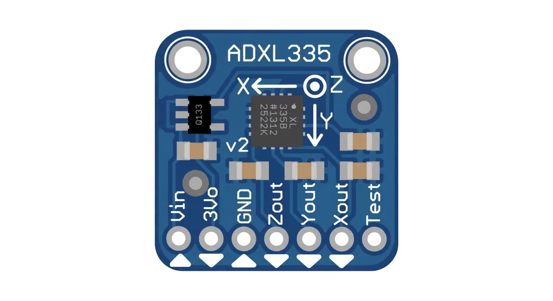
What is ADXL345 / MPU6050?
Accelerometers are sensors that measure acceleration forces: either static forces like gravity, or dynamic forces caused by motion, tilt, vibration, or shock. By measuring acceleration, they give your system spatial awareness.
Modern microcontrollers interact with chips like the ADXL345 (3-axis accelerometer) or the MPU6050 (which fuses an accelerometer with a gyroscope) to enable tilt sensing, drone flight stabilization, step counters, and gaming gesture inputs.
Key Features
3-Axis Sensing
Simultaneously tracks linear acceleration along the X, Y, and Z axes.
High Resolution
Supports user-selectable g-ranges (e.g., ±2g, ±4g, ±8g, ±16g) for varying sensitivities.
Ultra-Low Power
Consumes micro-amps of current, enabling long battery life in wearable devices.
I2C/SPI Interfaces
Communicates digitally with standard protocols, making it compatible with all modern microcontrollers.
Motion Interrupts
Hardware interrupt pins trigger on activity, inactivity, tap, double-tap, or free-fall.
Shock Resistance
High survivability up to 10,000g shock, ensuring durability under extreme conditions.
Pin Configuration
VCC
Power supply pin. Usually operates at 3.3V for sensor IC, but breakout boards often allow 5V input.
GND
Ground reference. Must connect to the common ground of your microcontroller.
SCL
Serial Clock Line. Synthesizes clock timing for I2C data transfer synchronization.
SDA
Serial Data Line. Digital bi-directional line for sending/receiving data registers.
CS
Chip Select. Input pin used to switch communication mode between I2C (HIGH) and SPI.
INT
Interrupt outputs. Pulses host microcontroller upon detecting click, shake, or free-fall.
How It Works
The Science Behind It
Accelerometers use MEMS (Micro-Electro-Mechanical Systems) technology. Inside the chip is a tiny mass suspended by silicon springs.
When the sensor moves, the mass shifts, changing the Capacitance between the moving mass and fixed electrodes. The chip converts this change into a voltage or digital signal representing acceleration in G-force.
Fundamental Physics & Calculation:
Force (F) = Mass (m) × Acceleration (a)

Capacitance Change (ΔC) ∝ Shift in Distance (d) ∝ Acceleration (a)
Wiring Tips & Best Practices
Voltage Levels
Most MEMS sensors operate at 3.3V logic. Connecting 5V directly to SDA/SCL pins can damage the sensor; use logic level shifters.
Solder Quality
Breakout boards need solid soldering on the header pins. Loose connections will interrupt I2C communication.
Pull-up Resistors
I2C lines require 4.7kΩ pull-up resistors to VCC. Check if your breakout board already has onboard pull-ups.
Interrupt Usage
Use interrupt pins (INT1/INT2) to wake the MCU from sleep mode rather than constantly polling register values.
Calibration Offset
Store fixed offset values in code to calibrate gravity offset (e.g. subtracting 1g on the Z-axis when flat).
Mounting Orientation
Mount the board firmly to the chassis. Vibration and relative movement will add high-frequency noise to your readings.