STM32 Blue Pill & STM32F103
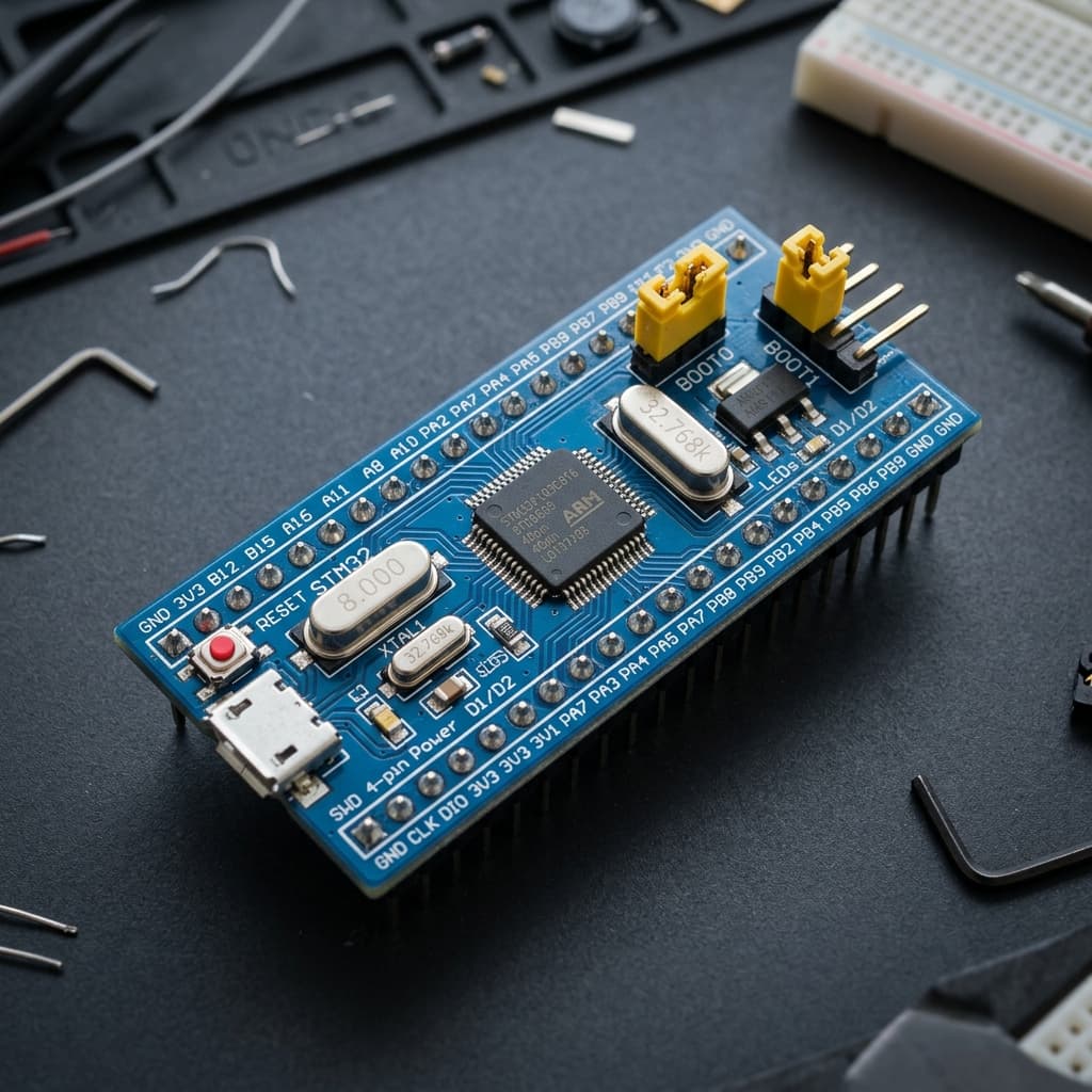
What is STM32 Blue Pill & STM32F103?
The STM32 Blue Pill is a legendary, low-cost minimum system development board powered by the STMicroelectronics STM32F103C8T6 32-bit ARM Cortex-M3 microcontroller running at 72 MHz. Long celebrated as the budget gateway into the 32-bit ARM embedded ecosystem, it delivers extraordinary computing performance at AVR prices.
Equipped with 64 KB (often 128 KB) of flash memory, 20 KB of SRAM, two high-speed 12-bit ADCs, USB 2.0 Full-Speed connectivity, and multiple 5V-tolerant I/O pins, the Blue Pill is widely used for industrial automation, real-time motor PID loops, and learning bare-metal register programming with STM32CubeIDE or Arduino.
Technical Specifications
Recommended Applications & Industry Uses
High-Speed Motor & Inverter Control
Advanced timer 1 generates complementary 3-phase PWM signals with programmable dead-time insertion for brushless DC (BLDC) motor drivers.
Automotive & CAN Bus Nodes
Built-in CAN 2.0B active controller interfaces directly with vehicle onboard diagnostics (OBD-II) networks and automotive telemetry.
USB Audio & MIDI Devices
Native USB 2.0 Full-Speed device controller enables low-latency USB MIDI keyboards, synthesized tone generators, and custom HID devices.
High-Precision Oscilloscopes & DAQs
Dual 12-bit 1 MSPS ADCs paired with circular DMA buffers sample analog signals at high frequencies without consuming CPU execution cycles.
Key Features & Architectural Highlights
ARM Cortex-M3 Processing
72 MHz 32-bitIncludes hardware integer multiplication and hardware division. Computes math and digital filtering algorithms up to 10x faster than traditional 8-bit AVR microcontrollers.
5V-Tolerant GPIO Lines
5V TolerantUnlike most 3.3V microcontrollers, many pins on the STM32F103 (marked FT) safely accept 5V digital logic inputs, protecting the board when interfacing with legacy sensors.
High-Precision 12-bit ADCs
Dual 12-bit 1MspsTwo independent 12-bit analog-to-digital converters deliver 4096 discrete resolution steps with ultra-fast 1 million samples per second sampling rates.
Single-Wire Debug Interface
SWD Hardware DebugStep through C/C++ firmware line-by-line, set live watch variables, and monitor memory using an inexpensive ST-Link V2 dongle and GDB.
Motor Control PWM Timers
Advanced TimersAdvanced-control timer (TIM1) features complementary PWM outputs and dead-time insertion, engineered specifically for 3-phase BLDC motor inverter bridges.
Automotive CAN Bus Native
CAN 2.0B BusIntegrated hardware CAN 2.0B active controller capable of transmitting and receiving automotive telemetry frames up to 1 Mbps.
Pin Configuration & Peripheral Layout
Digital GPIO Pins (PA0 - PB15, PC13 - PC15)
37 GPIO pins operating at 3.3V logic. Most pins accept up to 5V inputs without damage.
- Pins marked FT (Five-volt Tolerant) include PA8–PA15, PB3, PB4, PB6–PB9, PB12–PB15
- Pin PC13 connects to the onboard green/blue user LED (active LOW)
- Pins PA9 and PA10 serve as the primary USART1 serial programming interface
Dual 12-bit ADCs (ADC1 & ADC2)
10 external analog channels capable of synchronized dual-ADC simultaneous conversions.
- Channels ADC0 to ADC9 located on pins PA0 through PA7 and PB0, PB1
- Full 12-bit conversion delivers 0–4095 digital counts across 0V to 3.3V
- Direct connection to multi-channel DMA for autonomous analog sensor streaming
Hardware Communication & Debug
Multi-channel serial controllers, automotive CAN bus, and debug ports.
- 3 hardware USARTs, 2 SPI interfaces (up to 18 MHz), and 2 I2C interfaces (up to 400 kHz)
- Hardware CAN 2.0B bus on pins PB8 (RX) and PB9 (TX)
- SWD header pins: PA13 (SWDIO) and PA14 (SWCLK) for ST-Link programming
Communication Protocols
Hardware USART (x3)
PA9/PA10, PA2/PA3, PB10/PB11
Three independent serial ports supporting baud rates up to 4.5 Mbps with hardware RTS/CTS flow control.
Hardware SPI (x2)
SPI1 (18 MHz) & SPI2 (9 MHz)
High-speed SPI buses with DMA support for driving graphical LCD screens, high-speed ADCs, and SD cards.
Hardware I2C (x2)
I2C1 (PB6/PB7) & I2C2 (PB10/PB11)
Dual I2C buses supporting Standard and Fast (400 kHz) modes with SMBus and PMBus protocol compliance.
CAN 2.0B Controller
PB8 (CAN_RX) & PB9 (CAN_TX)
Automotive Controller Area Network peripheral with 14 filter banks, supporting 11-bit standard and 29-bit extended frames.
USB 2.0 Full Speed
PA11 (USB D-) & PA12 (USB D+)
12 Mbps on-chip USB peripheral for emulating virtual COM ports, USB MIDI keyboards, or mass storage devices.
SWD Debug Port
PA13 (SWDIO) & PA14 (SWCLK)
Two-pin ARM Serial Wire Debug protocol interface providing full hardware breakpoints and register stepping.
Advanced Topics & Expert Knowledge
ST-Link V2 SWD Flashing Workflow
Connect 4 wires (3.3V, GND, SWDIO, SWCLK) from an ST-Link V2 programmer to the Blue Pill header. Flash firmware instantly in VS Code or STM32CubeProgrammer.
Pro tip: SWD flashing bypasses the USB bootloader completely and allows setting live hardware breakpoints in GDB.
7-Channel Direct Memory Access (DMA)
Stream ADC conversions or UART buffers directly into SRAM without any CPU execution intervention using the 7-channel DMA controller.
Pro tip: Using DMA with ADC eliminates sampling jitter and frees 100% of CPU cycles for real-time control algorithms.
The USB R10 Pull-Up Resistor Mod
Many budget clone Blue Pill boards feature an incorrect 10kΩ or 4.7kΩ pull-up resistor on the USB D+ line (R10) instead of the required 1.5kΩ resistor.
Pro tip: If your computer fails to recognize the Blue Pill USB device, replace R10 or solder a 1.5k–1.8k resistor between PA12 and 3.3V.
Nested Vectored Interrupt Controller (NVIC)
The Cortex-M3 NVIC supports 16 programmable priority levels and sub-priorities, delivering ultra-low interrupt latency down to 12 clock cycles.
Pro tip: Higher priority interrupts can preempt lower priority ISRs, guaranteeing deterministic timing for motor shutoffs.
Automotive CAN Bus Interfacing
Pair the Blue Pill’s onboard CAN controller with an inexpensive MCP2551 or TJA1050 5V transceiver to read vehicle OBD-II diagnostics frames.
Pro tip: Remember to terminate both ends of the CAN bus with 120Ω resistors between CAN-H and CAN-L.
128 KB Undocumented Flash Bonus
Although labeled as STM32F103C8 (rated for 64 KB), the overwhelming majority of genuine ST silicon contains 128 KB of working physical Flash memory.
Pro tip: You can safely modify your linker script from 64K to 128K on almost all Blue Pill boards.
Recommended Applications & Industry Uses
High-Speed Motor & Inverter Control
Advanced timer 1 generates complementary 3-phase PWM signals with programmable dead-time insertion for brushless DC (BLDC) motor drivers.
Automotive & CAN Bus Nodes
Built-in CAN 2.0B active controller interfaces directly with vehicle onboard diagnostics (OBD-II) networks and automotive telemetry.
USB Audio & MIDI Devices
Native USB 2.0 Full-Speed device controller enables low-latency USB MIDI keyboards, synthesized tone generators, and custom HID devices.
High-Precision Oscilloscopes & DAQs
Dual 12-bit 1 MSPS ADCs paired with circular DMA buffers sample analog signals at high frequencies without consuming CPU execution cycles.
Programming on STM32 Blue Pill & STM32F103
📚 Official Citations & Technical References
To ensure the absolute accuracy and reliability of this guide, all specifications, pinouts, and register settings have been cross-verified with official manufacturer documentation:
Related Resources
Frequently Asked Questions
Why does my computer not detect the Blue Pill via the USB port?
Most clone Blue Pill boards do not come with a USB bootloader installed from the factory and feature an incorrect pull-up resistor on R10 (D+). Program the board using an ST-Link V2 programmer or a USB-to-UART converter on pins PA9/PA10.
Which pins on the STM32 Blue Pill are 5V tolerant?
Pins marked "FT" (Five-volt Tolerant) in the ST datasheet safely accept 5V digital logic inputs. These include PA8 through PA15, PB3, PB4, PB6 through PB9, and PB12 through PB15. Analog pins (PA0–PA7, PB0, PB1) are strictly 3.3V maximum.
What are the BOOT0 and BOOT1 jumpers used for?
The jumpers select the chip boot mode: (BOOT0=0, BOOT1=0) boots from User Flash memory (normal running mode). (BOOT0=1, BOOT1=0) activates the built-in factory ROM serial bootloader on USART1 (PA9/PA10). (BOOT0=1, BOOT1=1) boots from internal SRAM.