💡 DC Motor as a Generator
Spin a small DC motor by hand and power an LED with the electricity you generate — electromagnetic induction made visible.
Overview
Every DC motor is also a generator. This no-Arduino-needed experiment demonstrates Faraday's Law of Electromagnetic Induction: when you rotate a coil inside a magnetic field, it produces an EMF (electromotive force) that drives current through a circuit.
Technical Insight: A typical 3–6V DC hobby motor, when spun by hand at ~500 RPM, generates approximately 1–2V AC (rectified to DC by the commutator). This is enough to illuminate a red or green LED (forward voltage ~2V). The output is pulsating DC proportional to RPM — confirmed by the LED brightness changing with spin speed.
In simple terms: The same copper windings that normally push the motor shaft around, when spun externally, generate their own voltage through the same electromagnetic principle — just running in reverse. You are building a miniature power plant.
What you'll learn: Faraday's Law of Induction, back-EMF concept, energy conversion (mechanical → electrical), LED polarity, and why renewable energy turbines are just large versions of this exact principle.
Estimated time: 15-25 minutes (pure circuit, no code). Difficulty: ⭐ Beginner — great for science fair demonstration.
Components Needed
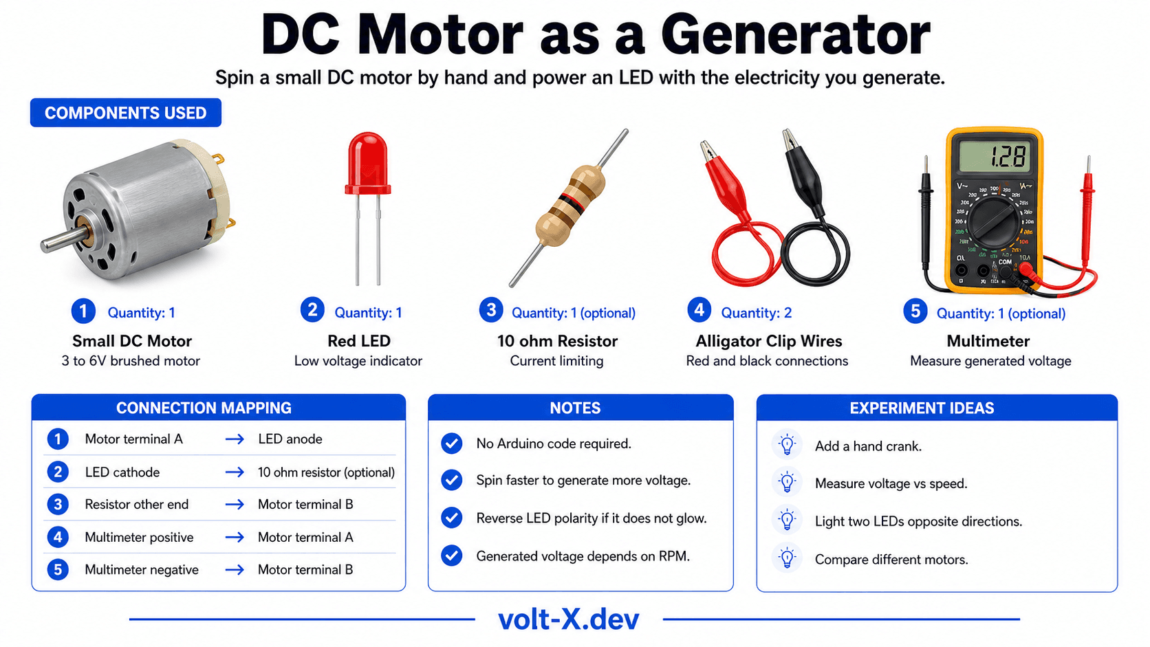
| Component | Specification | Qty | Notes |
|---|---|---|---|
| Small DC Motor | 3–6V, any hobby motor | 1 | NOT a stepper; must be brushed DC |
| Red LED | 2V forward voltage | 1 | Low voltage drop — works at ~1.8V |
| 10Ω Resistor (optional) | Current limiting | 1 | Protects LED from voltage spikes |
| Alligator Clip Wires | Red and Black | 2 | Connect motor terminals to LED |
| Multimeter (optional) | DC voltage | 1 | Measure generated voltage |
Component Pin Mapping
Step-by-Step Tutorial
Connect Motor to LED
Add Optional Resistor
Spin the Motor
Measure Voltage
Speed vs Brightness
Arduino Code
// DC Motor as Generator — No Arduino Needed!
// This is a pure circuit demonstration.

// === CIRCUIT CONNECTIONS ===
// Motor Terminal A  ──────── LED Anode (+)
//                               |
//                           LED (Red, 2V)
//                               |
// Motor Terminal B  ──────── LED Cathode (-) via 10Ω resistor

// === CONCEPT (No code required) ===
// When you spin the motor shaft:
//   - Rotating magnets induce EMF in copper windings
//   - Commutator rectifies AC to pulsating DC
//   - Generated voltage ≈ 0.01V × RPM (approximate)
//   - At ~300 RPM: ~3V → enough to light an LED!

// === Optional Arduino monitoring version ===
// Connect motor terminals to A0 and GND
// Measure the generated voltage in code:

void setup() { Serial.begin(9600); }
void loop() {
  float v = analogRead(A0) * (5.0 / 1023.0);
Serial.print("Generated Voltage: "); Serial.print(v, 3); Serial.println(" V");Reviews & Ratings
Sign in to leave a review
Loading reviews...