🔋 Arduino Digital Voltmeter
Turn your Arduino into a precision voltmeter — measure 0 to 25V DC using a resistor voltage divider and live LCD display.
Overview
A digital voltmeter converts an analog voltage into a readable number. Arduino's built-in 10-bit ADC can measure voltages from 0 to 5V directly — but with a simple resistor divider, we extend the range to 0–25V.
Technical Insight: The voltage divider uses two resistors (R1=30kΩ, R2=7.5kΩ) to scale the input voltage down by a factor of 5. So 25V input becomes 5V at the Arduino pin, 10V becomes 2V, etc. The formula is: V_in = V_read × (R1+R2)/R2.
In simple terms: We 'shrink' the input voltage to a safe range Arduino can read, then 'stretch' the reading back to the original value in code — like scaling a map.
What you'll learn: Voltage divider design and math, ADC resolution and accuracy, analogRead(), I2C LCD integration, and real-world calibration techniques.
Estimated time: 35-50 minutes. Difficulty: ⭐⭐ Easy — great for electrical lab coursework.
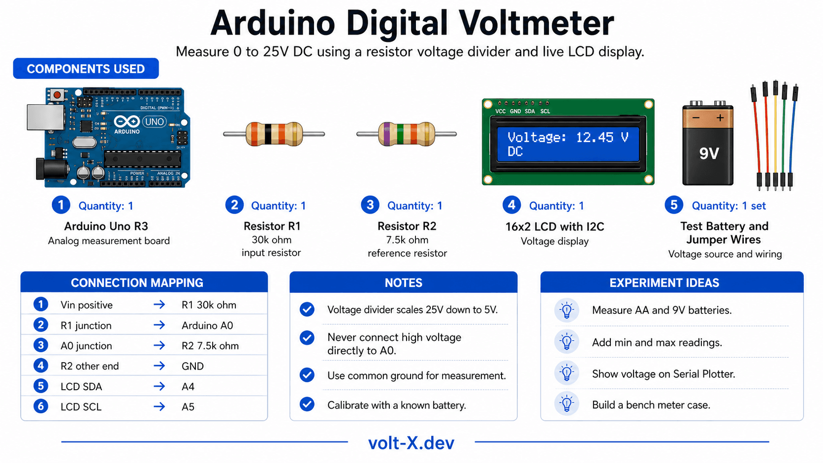
Components Needed
| Component | Specification | Qty | Notes |
|---|---|---|---|
| Arduino Uno R3 | 5V | 1 | |
| Resistor R1 | 30kΩ (use 3×10kΩ in series) | 1 | Input voltage divider |
| Resistor R2 | 7.5kΩ (use 10kΩ || 30kΩ) | 1 | Divider reference |
| 16x2 LCD with I2C | HD44780 + PCF8574 | 1 | Or use Serial Monitor only |
| Breadboard + Wires | Half-size | 1 | |
| Test Battery/PSU | Up to 25V DC | 1 | Source to measure |
Component Pin Mapping
Step-by-Step Tutorial
Build the Voltage Divider
Install LCD Library
LiquidCrystal_I2C by Frank de Brabander via Library Manager.Connect the LCD
Upload Code
Calibrate
CALIB constant in the code for maximum accuracy.Arduino Code
// Digital Voltmeter — Volt X
// Voltage divider: R1=30kΩ, R2=7.5kΩ → measures 0-25V

#include <Wire.h>
#include <LiquidCrystal_I2C.h>

LiquidCrystal_I2C lcd(0x27, 16, 2);

const float R1     = 30000.0; // 30kΩ
const float R2     = 7500.0;  // 7.5kΩ
const float CALIB  = 1.00;    // Fine-tune for accuracy
const int   VPIN   = A0;

float readVoltage() {
  long sum = 0;
  for (int i = 0; i < 10; i++) { sum += analogRead(VPIN); delay(5); }
  float vRaw = (sum / 10.0) * (5.0 / 1023.0);
  return vRaw * ((R1 + R2) / R2) * CALIB;
}

void setup() {
  lcd.init(); lcd.backlight();
  lcd.setCursor(0, 0); lcd.print("  Volt X Meter  ");
  Serial.begin(9600);
}Reviews & Ratings
Sign in to leave a review
Loading reviews...