🤖 Line Follower Robot
Build a 2-wheel robot that autonomously tracks a black line on white paper using IR sensors and an L298N motor driver.
Overview
A line follower robot reads the contrast between a black line and a white surface using infrared sensors and steers its wheels accordingly. It is the classic entry-point into autonomous robotics.
Technical Insight: IR sensors emit 940nm infrared light. White surfaces reflect ~90% of IR, keeping the photodiode output LOW. Black surfaces absorb IR, returning HIGH. By placing two sensors at the front, the robot knows which side has crossed the line and corrects its path in milliseconds.
In simple terms: Left sensor on black AND right on white → the robot has drifted right → steer left (slow left motor). Both on white → straight ahead. Both on black → stop or search. It's reflexive intelligence with only 2 bits of data.
What you'll learn: IR sensor interfacing, motor driver H-bridge direction control, conditional logic for autonomous steering, and robot chassis assembly basics.
Estimated time: 60-90 minutes. Difficulty: ⭐⭐⭐ Intermediate — your first fully autonomous robot!
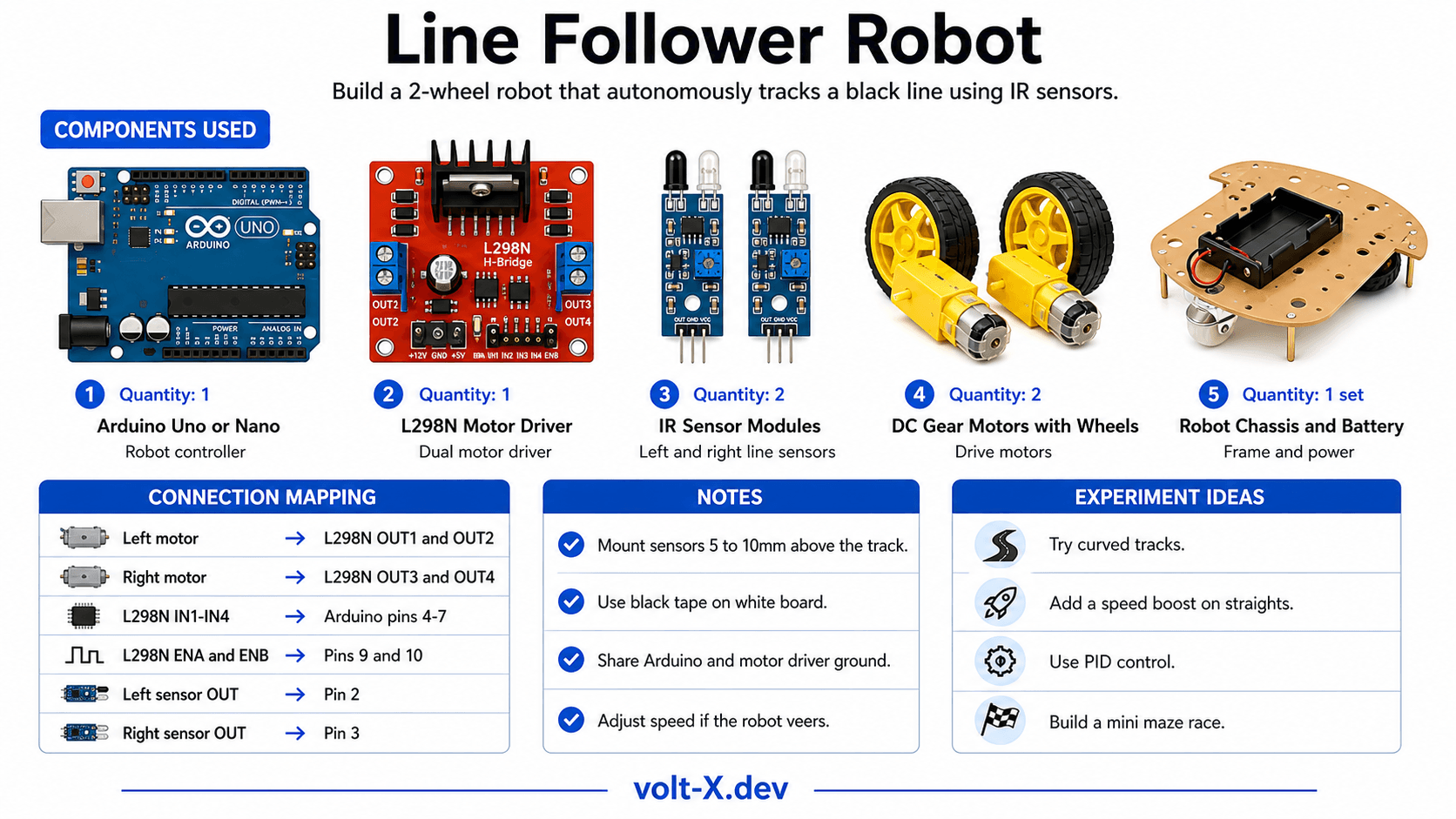
Components Needed
| Component | Specification | Qty | Notes |
|---|---|---|---|
| Arduino Uno R3 / Nano | 5V | 1 | Nano fits better on chassis |
| L298N Motor Driver | 2A dual H-bridge | 1 | |
| IR Sensor Modules | TCRT5000 or FC-51 | 2 | Left and right sensors |
| DC Gear Motors | 6V, 100-200 RPM | 2 | With wheels attached |
| Robot Chassis | 2WD kit or DIY cardboard | 1 | |
| 9V or 12V Battery | With connector | 1 | Motor power supply |
| Jumper Wires | M-M and F-M | 20 |
Component Pin Mapping
Step-by-Step Tutorial
Assemble the Chassis
Wire the L298N
Mount and Wire IR Sensors
Draw a Track
Upload and Calibrate
Arduino Code
// Line Follower Robot — Volt X
// 2 IR sensors, L298N motor driver

// Motor Driver Pins
const int ENA = 9,  IN1 = 4,  IN2 = 5; // Left motor
const int ENB = 10, IN3 = 6,  IN4 = 7; // Right motor

// IR Sensor Pins (LOW = black line detected)
const int IR_LEFT  = 2;
const int IR_RIGHT = 3;

const int BASE_SPEED = 200; // 0-255 PWM speed

void setMotors(int lSpeed, int lDir, int rSpeed, int rDir) {
  analogWrite(ENA, lSpeed);
  digitalWrite(IN1, lDir);  digitalWrite(IN2, !lDir);
  analogWrite(ENB, rSpeed);
  digitalWrite(IN3, rDir);  digitalWrite(IN4, !rDir);
}

void setup() {
  pinMode(IN1,OUTPUT); pinMode(IN2,OUTPUT);
  pinMode(IN3,OUTPUT); pinMode(IN4,OUTPUT);
  pinMode(IR_LEFT, INPUT); pinMode(IR_RIGHT, INPUT);
Serial.begin(9600);Reviews & Ratings
Sign in to leave a review
Loading reviews...