🔌 Relay Module Switch
Safely control 230V AC appliances from a 5V Arduino signal using a relay module — understand high-voltage isolation.
Overview
A relay is an electrically operated switch. A small Arduino signal energizes an internal electromagnet, which physically flips a metal contact to connect or disconnect a high-power circuit — giving total isolation between the low-voltage control side and the mains AC side.
Technical Insight: The relay module includes a BC817 transistor driver, 1N4148 flyback protection diode, and LED indicator. When Arduino drives the IN pin LOW (active-low), the transistor switches 75mA through the relay coil, pulling the armature and switching contacts rated at 10A/250VAC — a 1000× current amplification from a 10mA Arduino output.
In simple terms: Think of the relay as a TV remote controlling your TV. The small remote signal (Arduino) controls the big device (230V appliance) without ever touching its high-voltage wiring.
What you'll learn: Relay module wiring (NO/NC/COM), flyback diode importance, active-low vs active-high control logic, timed on/off scheduling, and high-voltage safety practices.
Estimated time: 30-40 minutes. Difficulty: ⭐⭐ Easy — but requires caution with the AC side.
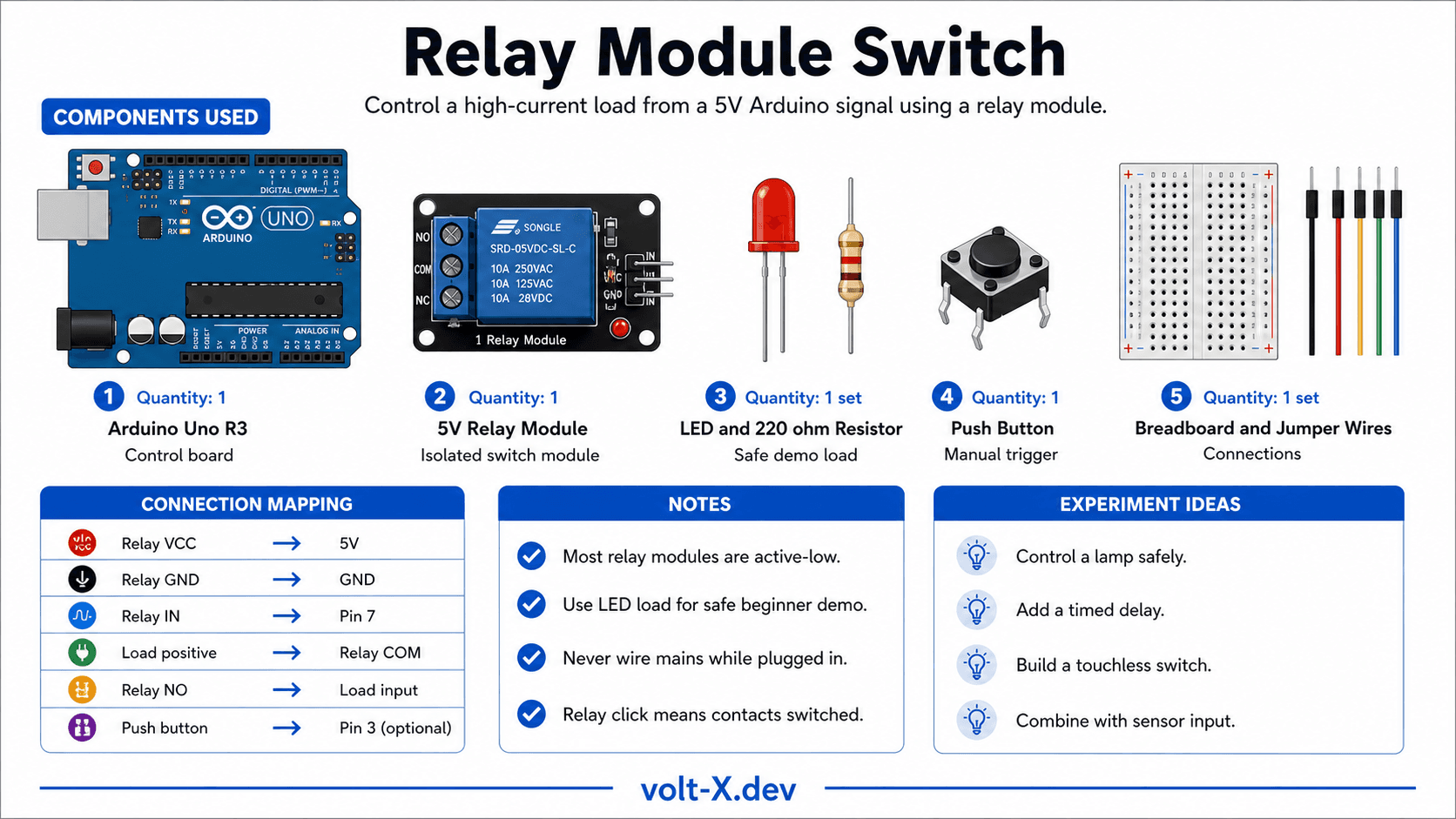
Components Needed
| Component | Specification | Qty | Notes |
|---|---|---|---|
| Arduino Uno R3 | 5V | 1 | |
| 5V Relay Module | 1-channel, SRD-05VDC-SL-C | 1 | With built-in driver |
| LED + Resistor | 220Ω, any color | 1 | Simulate AC load (safe demo) |
| Push Button | Momentary SPST | 1 | Manual trigger (optional) |
| Breadboard + Wires | Half-size | 1 |
Component Pin Mapping
Step-by-Step Tutorial
Wire Control Side
Connect LED Load (Safe Demo)
Upload Blink-Relay Code
AC Wiring (Advanced – supervised only)
Add Button Control
Arduino Code
// Relay Switch — Volt X
// Relay IN pin is ACTIVE-LOW (LOW = relay ON)

const int RELAY_PIN = 7;
const int BTN_PIN   = 3;

bool relayState = false;
bool lastBtn    = HIGH;

void setup() {
  pinMode(RELAY_PIN, OUTPUT);
  pinMode(BTN_PIN, INPUT_PULLUP); // Use internal pull-up
  digitalWrite(RELAY_PIN, HIGH);  // Start with relay OFF (active-low)
  Serial.begin(9600);
  Serial.println("Relay Switch — Volt X");
}

void loop() {
  bool btn = digitalRead(BTN_PIN);

  // Toggle on button press (falling edge)
  if (btn == LOW && lastBtn == HIGH) {
    relayState = !relayState;
    digitalWrite(RELAY_PIN, relayState ? LOW : HIGH); // active-low
Serial.println(relayState ? "Relay ON" : "Relay OFF");Reviews & Ratings
Sign in to leave a review
Loading reviews...